
R0.2 Design (draft)
The second
release will perform shape or mesh manipulation, and will result in having complex shapes from primitive shapes. You may see at the next and at the end of this post, the current design and implementation results.
I start with the initial concept of generating random primitive 2D shapes, merging them into one that follows the outside perimeter of all, and then extruding vertically in the y axis as in R0.1. The following 2 figures represent these simple steps.
Generating primitive shapes and placing them on a
plane can be done in a lot of different ways. I will describe a really
simple randomisation algorithm and you can play with the current implementation prototype below:

 First, I will define a vocabulary of primitive shapes, that is a mapping from a character to a shape, as follows:
I will add to this soup some operations as well, part of the Operations set O:
Operations are parametric, meaning that they require some parameter in order to be valid. For 2D transformations as is the case with this step, we will need the following parameters for each one:
t{R24}(2.0,4.0) Similarly the notation s{C12}(3.5) means that the 12th circle should be scaled up by 3.5 times.
A string T will be appended at each iteration with the transformation(s) that were selected to be applied.
Initially, we start with the creation of a random shape. Its rotation will be 0 degrees and its scale will be 1 in all axis, just like creating a new 3D primitive shape in a Unity scene.
T(t) = T(t-1) + "c{R1}(0, 0)"
+ here stands for string concatenation.
Each time a shape is created, it is added to the pool of shapes, let this set be H. H collects instances of shapes and not types of shapes, so it is not to be confused with S. Initially H would be empty.
Then at each iteration we may randomly pick up an operation from O and apply it to a random shape in H (or in S if we are creating a new shape), like the following pseudocode presents for iteration k:
operation = Random(operation from O)
if (operation == "c") then
shape = Random(shape from S)
else
shape = Random(shape from H)
if (operation == "t" OR operation == "w") then
S(k) = operation{shape}(Random(float), Random(float))
else if (operation == "r" OR operation =="s") then
S(k) = operation{shape}(Random(float))
Randomness is a good thing, but in order to achieve manageable results, one has to bound randomisation of continuous variables such as the 2D and 1D float parameters. I will try to implement such a bounded randomisation so that:
The implementation of R0.2 will follow the Factory pattern method for the creation of different shapes, building on top of the design of release R0.1. This is a popular software pattern for constructing different kinds of objects. ShapeFactory is an abstract class that is inherited by a set of other classes that help with the instantiation of objects of different shapes. I am hereafter including a UML class diagram depicting the dependencies of the main classes:
 Note: The diagram is made with WhiteStarUML, an open source CASE tool for software design with the UML graphical modelling language.
You may have observed that new classes inherit from ShapeFactory in comparison to the class diagram of R0.1, being able to construct new primitive shape types, namely TriangularShapeFactory and CircularShapeFactory. Same is true for commands as well, and the new classes ShapeTranslate, ShapeRotate, ShapeScale inherit from the abstract ShapeCommand, and are in a generalisation relationship with it.
Merging however several 2D shapes into one common outline is not so simple task as you might think. The operation is called Boolean Addition (of 2 or more solids) in many 3D modelling tools, and now that I am writing these lines, I am having second thoughts about this. I may go for extruding each shape separately, we will see.
More on this soon...
I start with the initial concept of generating random primitive 2D shapes, merging them into one that follows the outside perimeter of all, and then extruding vertically in the y axis as in R0.1. The following 2 figures represent these simple steps.
 |
| step1: generate simple primitive 2D shapes on the floor level, here 3 shapes overlapping one another |
 |
| step2: extrude edges vertically into walls (again the outline here is offset down the y axis for visibility purposes) |
Unity Web Player | Final Results for release R02
- "R": Rectangle
- "T": Triangle
- "C": Circle
I will add to this soup some operations as well, part of the Operations set O:
- "t": Translate
- "r": Rotate
- "s": Scale
- "w": Skew
- "c": Create new
- "d": Delete
Operations are parametric, meaning that they require some parameter in order to be valid. For 2D transformations as is the case with this step, we will need the following parameters for each one:
- For translation: One 2d vector to define the distance between the initial and final position
- For rotation: One float, the (Euler) angle of the rotation between initial and final rotation
- For scaling: One float, to represent the scaling factor between initial and final scale
- For skewness: One 2D vector to represent the skewing distance between initial and final transformation
- For shape creation: One 2D vector for position
t{R24}(2.0,4.0) Similarly the notation s{C12}(3.5) means that the 12th circle should be scaled up by 3.5 times.
A string T will be appended at each iteration with the transformation(s) that were selected to be applied.
Initially, we start with the creation of a random shape. Its rotation will be 0 degrees and its scale will be 1 in all axis, just like creating a new 3D primitive shape in a Unity scene.
T(t) = T(t-1) + "c{R1}(0, 0)"
+ here stands for string concatenation.
Each time a shape is created, it is added to the pool of shapes, let this set be H. H collects instances of shapes and not types of shapes, so it is not to be confused with S. Initially H would be empty.
Then at each iteration we may randomly pick up an operation from O and apply it to a random shape in H (or in S if we are creating a new shape), like the following pseudocode presents for iteration k:
operation = Random(operation from O)
if (operation == "c") then
shape = Random(shape from S)
else
shape = Random(shape from H)
if (operation == "t" OR operation == "w") then
S(k) = operation{shape}(Random(float), Random(float))
else if (operation == "r" OR operation =="s") then
S(k) = operation{shape}(Random(float))
Randomness is a good thing, but in order to achieve manageable results, one has to bound randomisation of continuous variables such as the 2D and 1D float parameters. I will try to implement such a bounded randomisation so that:
- translation vector magnitude does not surpass 30% of the shape's perimeter
- rotation angle should stay in the [-30, +30] degrees range
- scaling vector is within the [0.7, 1.3] range for each axis X and Z
The implementation of R0.2 will follow the Factory pattern method for the creation of different shapes, building on top of the design of release R0.1. This is a popular software pattern for constructing different kinds of objects. ShapeFactory is an abstract class that is inherited by a set of other classes that help with the instantiation of objects of different shapes. I am hereafter including a UML class diagram depicting the dependencies of the main classes:

You may have observed that new classes inherit from ShapeFactory in comparison to the class diagram of R0.1, being able to construct new primitive shape types, namely TriangularShapeFactory and CircularShapeFactory. Same is true for commands as well, and the new classes ShapeTranslate, ShapeRotate, ShapeScale inherit from the abstract ShapeCommand, and are in a generalisation relationship with it.
Merging however several 2D shapes into one common outline is not so simple task as you might think. The operation is called Boolean Addition (of 2 or more solids) in many 3D modelling tools, and now that I am writing these lines, I am having second thoughts about this. I may go for extruding each shape separately, we will see.
R0.2 Enough said, where is the code, dude?
I will release the scripting code progressively, so that I will be able to properly comment on it and explain things.Public and Private Variables
In view of the simple initialisation of R0.1, I have introduced here some public variables that control the generation of shapes. These are explained below:- useTriangles: enables (if true) or disables (if false) the generation of triangle primitives
- useRectangles: enables (if true) or disables (if false) the generation of rectangle primitives
- useCircles: enables (if true) or disables (if false) the generation of triangle primitives
- useTranslation: enables (if true) or disables (if false) the translation of existing 2D shapes in the scene
- useRotation: enables (if true) or disables (if false) the rotation of existing 2D shapes in the scene
- useScaling: enables (if true) or disables (if false) the scaling (re-sizing) of existing 2D shapes in the scene
- useSkewing: enables (if true) or disables (if false) the skewing of existing 2D shapes in the scene. This option is ignored since I have not implemented skewing yet
- maximumIterations: the number of iterations where the shape generation algorithm will be running. After this threshold the algorithm terminates.
- currentIteration: holds the current number of iterations, used to compare with maximumIterations in order to know when to stop the shape generation algorithm
- triangularFactory, rectangularFactory, circularFactory: instances of the respective shape factories, one per class. These instances will be used throughout the script to instantiate (spawn) the different shapes on the XZ plane in the scene.
- acceptableShapes: an array of shapes that the randomisation algorithm will choose from. It actually implements a user-based shape filter and is based on the user input of the public variables useTriangles, useRactangles, useCircles
- acceptableCommands: an array of commands that the randomisation algorithm will choose from to apply on existing shapes. It implements a user-based filter and is based on the user input of the public variables useTranslation, useRotation, useScaling.
/*
 * Project Name: Procedural Buildings
 * Scene Name: MainScene
 * Version: R0.3
 * Date: May 2013
 * Script Author: Elias Kalapanidas
 *
 * Objective: Procedural Generation of as-much-as-possible realistic buildings, to be used in a procedurally generated city (a destractibe urban environment)
 */

using UnityEngine;
using System.Collections;
using System.Collections.Generic;

public class buildingBaseLayoutGeneration : MonoBehaviour {
 public bool useTriangles = true;
 public bool useRectangles = true;
 public bool useCircles = true;
 public bool useTranslation = true;
 public bool useRotation = true;
 public bool useScaling = true;
 public bool useSkewing = false;
 public int maximumIterations = 6;

 private int currentIteration = 0;
 private TriangularShapeFactory triangleFactory = new TriangularShapeFactory();
 private RectangularShapeFactory rectangularFactory = new RectangularShapeFactory();
 private CircularShapeFactory circularFactory = new CircularShapeFactory();

 // acceptableShapes is the subset of shape primitives that the user has accepted to be included in generative modeling of 2D base layout shape, out of the available ones.
 private bool [] acceptableShapes;
 // acceptableCommands are the subset of operators/commands that the user has accepted to be applied on the set of acceptableShapes from the available ones
 private bool [] acceptableCommands;
Initialisation
 // Use this for initialization
 void Start () {
  acceptableShapes = new bool [3];
  acceptableShapes[(int)ShapeEnum.Triangle] = useTriangles;
  acceptableShapes[(int)ShapeEnum.Rectangle] = useRectangles;
  acceptableShapes[(int)ShapeEnum.Circle] = useCircles;
  // We cannot have all shape types de-activated. If this is the case, then automatically activate Rectangles and Log for the user to know
  if (!useTriangles && !useRectangles && !useCircles) {
   useRectangles = true;
   Debug.LogWarning("You have configured the Building Generator script to generate no shape types at all. Your choice is overriden with Rectangles activated.");
  }

  acceptableCommands = new bool [6];
  acceptableCommands[(int)CommandEnum.create] = true;
  acceptableCommands[(int)CommandEnum.translate] = useTranslation;
  acceptableCommands[(int)CommandEnum.rotate] = useRotation;
  acceptableCommands[(int)CommandEnum.scale] = useScaling;
  acceptableCommands[(int)CommandEnum.skew] = false; // ToDo: support skew in later versions/updates
  acceptableCommands[(int)CommandEnum.delete] = false; // ToDo: support shape deletion in later versions/updates

  //TriangularShape triangle = new TriangularShape();
  //CircularShape circle = new CircularShape(32);
 }
On update
I have inserted the code for each iteration in the Update method of the buildingBaseLayoutGeneration_R02 class. This means that each iteration, during which a new shape is created or an existing shape is transformed, will occur when a frame is refreshed.
About enum types in C#
A note on how random shapes and commands (operations on shapes) are selected: Shapes and command types are represented by 2 different enumerations: ShapeEnum and CommandEnum respectively.
Enumerators in an enum type are also assigned to integer variables, either explicitly by the user or implicitly by the order that they are defined. By default the first enumerator is assigned to 0, this is why I did not make that explicit. For example the enumeration enum ShapeEnum {Triangle, Rectangle, Circle} defaults to enum ShapeEnum {Triangle = 0, Rectangle = 1, Circle = 2};
Now if I declare
enum randomShape = ShapeEnum.Rectangle;
that would also mean that randomShape has also been assigned to 1. If I properly cast the variable such as (int)randomShape and print it in the Output, I will get 1. More interestingly so, the inverse also applies: If I declare:
int randomShape = 1;
then I can cast it as (ShapeEnum)randomShape, print it, and get the string "Rectangle". This proves that effectively the integer value has been assigned the correct enumerator, and then was converted to string in order to printed.
The enum type in CSharp is a strange beast: While it should be, it is not IEnumerable. You cannot search through the enumerators with a foreach (ShapeEnum aShape in ... In .Net usually you can write Enum.GetValues(Typeof(ShapesEnum)), and this would return an array of all the enumerators. However this did not work for me. Perhaps it is a limitation of the Mono implementation of .Net that is used in Unity.
Anyway, randomShape and randomCommand are 2 variables that get a random integer
value between the integer value of the first and last enumerator. I use them to get a random integer value within the range of the enumerators. If this value corresponds however to a shape or command that the user has deactivated (in the Inpector window), I am cycling through all enumerators until I find one that is active and valid (this is happening in lines 78-84 for commands and in lines 88-93 for shapes). After getting valid random values, then I convert them through casting to the enum type (in lines 102, 105, 108, 116).
 // Update is called once per frame
 void Update () {
  //Randomiser of acceptableCommands and acceptableShapes

  // First check if the maximumIteration number is met. If yes, stop the further shape generation
  if (currentIteration < maximumIterations) {
   // if this is the first iteration and there are no shapes generated yet, then
   // let the first command be "create"
   int randomCommand = 0;
   if (currentIteration == 0)
    randomCommand = (int)CommandEnum.create;
   else
    // else choose a random command
    randomCommand = Random.Range(0, acceptableCommands.Length);
   if (randomCommand >= acceptableCommands.Length) {
    Debug.LogError("random value selected for the command exceeds the number of available commands");
    randomCommand = 0;
   }
   // check if it is accepted, otherwise move on to the next in the list of acceptableCommands
   while (!acceptableCommands[randomCommand]) {
    // 6 below is the length of the CommandEnum enumeration variable
    if (randomCommand < acceptableCommands.Length -1) // for some mysterious reason Enum.GetNames().Length is not accepted by mono compiler
     randomCommand++;
    else
     randomCommand = 0; //cycle back to the beginning of the enum structure
   }
   // choose a random shape type
   int randomShape = Random.Range(0, acceptableShapes.Length);
   // check if it is accepted, otherwise move to the next in the list
   while (!acceptableShapes[randomShape]) {
    if (randomShape < acceptableShapes.Length -1) // Enum.GetNames().Length
     randomShape++;
    else
     randomShape = 0;
   }
   if (randomShape >= acceptableShapes.Length) {
    Debug.LogError("random value selected for the shape exceeds the number of available shapes");
    randomCommand = 0;
   }

   // declare a general ShapeFactory variable that will point to a given factory later on
   ShapeFactory abstractedFactory = null;
   //
   if ((ShapeEnum)randomShape == ShapeEnum.Triangle) {
    abstractedFactory = triangleFactory;
   }
   if ((ShapeEnum)randomShape == ShapeEnum.Rectangle) {
    abstractedFactory = rectangularFactory;
   }
   if ((ShapeEnum)randomShape == ShapeEnum.Circle) {
    abstractedFactory = circularFactory;
   }

   // execute randomCommand, but first find out which one in the enum the command is
   if ((CommandEnum)randomCommand == CommandEnum.create) {
    // and now, create a new shape of the selected randomShape type
    ShapeCreate create = new ShapeCreate();
    create.setShapeType( (ShapeEnum)randomShape );
    create.setShapeFactory(abstractedFactory);
    create.execute();
   }
   else
   {
    // choose a random shape instance from existing ones of type randomShape
    int randomShapeInstance = Random.Range(0, abstractedFactory.getShapesCount() -1);
    // perform the operations below only if the selected factory includes at least one shape
    if ((CommandEnum)randomCommand == CommandEnum.translate && abstractedFactory.getShapesCount()>0) {
     ShapeTranslate translate = new ShapeTranslate();
     translate.setShapeToTransform (abstractedFactory.getShape (randomShapeInstance));
     translate.execute ();
    }
    if ((CommandEnum)randomCommand == CommandEnum.rotate && abstractedFactory.getShapesCount()>0) {
     ShapeRotate rotate = new ShapeRotate();
     rotate.setShapeToTransform(abstractedFactory.getShape (randomShapeInstance));
     rotate.execute();
    }
    if ((CommandEnum)randomCommand == CommandEnum.scale && abstractedFactory.getShapesCount()>0) {
     ShapeScale scale = new ShapeScale();
     scale.setShapeToTransform (abstractedFactory.getShape (randomShapeInstance));
     scale.execute();
    }

   }
   currentIteration++;
  }
 } // Update() ends here

}; // buildingBaseLayoutGeneration class ends here
Some randomisation results
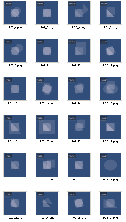
After making small amendments to the code above (e.g. adding a transparent material to the created shapes, automatically generating screen capture files and saving them in a folder), I have been able to get some results of different randomisation configurations. The image below displays a tile set of screen captures, each being the output of the algorithm set to run for 6 iterations, all shapes are on, the basic commands creation, translation, rotation and scaling are on as well.
 |
| results for 6 iterations, all 3 shapes, TRS transformations |
First conclusions:
- The shapes are largely overlapping one another
- Disproportional scaling seems nice (seen for example in R02_23)
- The limitations that I have set for the transformation commands (e.g. to scale only upwards, by a rate between 0% and 100%) is restricting the visual variation of possible transformations
- Apply all transformations at once on a given shape: first decide whether or not to apply a transformation (50% chance to apply), then proceed with it, otherwise proceed to the next one. This alteration will probably produce more interesting visual results, will reduce the concentration of shapes.
- Add a mirror command, to mirror a given shape across any random 2D direction.
- Loose the transformation boundaries
 |
| triple extrusion on a circle primitive |
Another observation I have is that something fishy is going on with the normal vectors. I will need to take a closer look.
After some time working with the script, I made some changes:
- The shape creation command also translates the shape, and dispositions it a bit away, to a random direction
- No extrusion is occuring while the randomisation algorithm is running. After the last iteration, all shapes are extruded along the +Y axis
- The boundaries of the 3 possible transformations are loosened a bit.
- The user defines a probability of occurance for each shape type and command, instead of a boolean activation/deactivation. This is used in the new randomisation mechanism (see below)
- A new randomisation mechanism is introduced, which is based on "Probability proportional to Size Sampling". I will explain this later on.


Probability-proportional-to-size-based sampling
This is my implementation of a statistical sampling process that is used in this project as a randomisation mechanism. I did not want to have a truly random process from a normal distribution. I would like to give the user the ability to assign to the shape types different probabilities of selection, the sum of which would equal 1. Similarly, the user would set the probabilities of selection for the different commands as well.
Let me show this with the example of the shape selection:
There are three shape types in the ShapeEnum enumeration. Say that the probabilities of selection are as follows:
P(Triangle) = 0.3
P(Rectangle) = 0.5
P(Circle) = 0.2
The sum of all probabilities is 1. Each shape contributes to the sum with its probability, and if we draw stacked the probabilities from 0 to 1, we can identify "zones" each corresponding to a different shape type:

I select a random float number in the range [0, 1]. This is what Random.Range(0, 1f) is doing. Say again that this random float equals 0.57. Now I would like to know the integer index that corresponds to the index of the selected zone. In the example above, this is 1 (remember that this is a 0-based index). This index is associated with the ShapeEnum enumeration, and it is assigned to the 2nd enumerator (Rectangle). The algorithm continues normally from that point on, after having selected the shape to be created or transformed by the commands.
 // Define Probability proportional to Size Sampling class
 public class PPSSampling {
  private ArrayList _probabilities;

  public void setProbability(float prob) {
   if (_probabilities == null)
    _probabilities = new ArrayList();
   _probabilities.Add(prob);
  }
  public int getRandomInt() {
   float greatSum = 0;
   for (int i=0; i<_probabilities data-blogger-escaped-.count="" data-blogger-escaped-float="" data-blogger-escaped-for="" data-blogger-escaped-greatsum="" data-blogger-escaped-i="" data-blogger-escaped-if="" data-blogger-escaped-int="" data-blogger-escaped-probabilities.count="" data-blogger-escaped-probabilities="" data-blogger-escaped-randomfloat="" data-blogger-escaped-randomprobzone="-1;" data-blogger-escaped-sumsofar="0;">= sumSoFar && randomFloat < (sumSoFar + (float)_probabilities[i]))
     randomProbZone = i;
    sumSoFar += (float)_probabilities[i];
   }
   return randomProbZone;
  }
 }
Next Idea to develop:
While I was playing out in the sun with my son, I got hit by another idea that has even more potential in generating interesting outlines: Why generating different shapes and then try to unite them in one with a boolean addition, and not try to apply the operations at the vertex level of one main shape? The idea is based on one of the foundational and simpler randomisation techniques: midpoint displacement. This technique works by introducing a new vertex in between two adjacent (neighbouring) vertices, and then by displacing it a bit to a random direction and by a random distance.By extending this idea, I could generate a simple rectangle, and then apply the following operations in a random fashion:
- Vertex displacement: translate a vertex
- Edge/ Nearest neighbours displacement: translate 2 or more neighbouring vertices
- Midpoint generation: generate a new vertex in the middle of 2 neighbouring vertices
- Primitive generation: select one edge (2 neighbouring vertices) and introduce a set of vertices that form a primitive shape. Possible subclasses:
- rectangle (2 vertices equally displaced)
- circle (a half-circle having its centre on the middle of the edge)
- triangle (3 vertices, 2 of which lie on the edge)
- select a subset of the vertices, mirror them across a random plane, and delete the remaining ones

Yet another change in plans: From vertex to edge-based manipulation
Well, before the ink of my vertex-based manipulation ideas dries, I am indulging into another angle to this problem:Instead of going to the vertex level, stay at the edge level: manipulate edges in 2 dimensions. The following concepts depict this idea, which I have already started implementing it. I am very optimistic if not confident that the results will be much better than before.

- The first figure depicts the result of extruding an edge, the extruded rectangle is stored as a submesh;
- The second figure is both extrusion and scaling of an edge, again the extruded trapezoid is stored as a submesh;
- The third figure is extrusion and midpoint merging of the extruded vertices, the extruded triangle is stored as a submesh.
Here is a nice result after 5 iterations (the first created the main shape, the 4 successive ones extruded a randomly selected outer edge).

Finally, after another implementation iteration (another sprint), the following results have come out, which I believe are more satisfying:
 |
| Randomisation with edge selection and extrusion (ShapeExtrudeRectangle class and operation), after 6 iterations |
After a simple check for overlaps with other existing triangles, and after implementing extrusion and midpoint merging, extrusion and scaling, I got the following results:
 |
| All horizontal extrusion operations applied randomly, after 6 iterations |
 public class ShapeExtrudeHorizontal : ShapeCommand {
  public enum ExtrusionType {rectangle, triangle, trapezoid};
  protected GameObject _shape;
  protected Vector3 _fromVertex, _toVertex;
  protected float _extrusionDistance;
  protected ExtrusionType _extrusionType;
  protected float _extrusionOffset;

  public ShapeExtrudeHorizontal () {
   _class = CommandEnum.extrudeHorizontal;
   _fromVertex = new Vector3(0,0,0);
   _toVertex = new Vector3(0,0,0);
   _extrusionDistance = 0f;
   _extrusionType = ExtrusionType.rectangle;
   _extrusionOffset = 0f;
  }

  public void setExtrusionDistance(float distance) {
   if (distance > 0)
    _extrusionDistance = distance;
  }
  public float getExtrusionDistance() { return _extrusionDistance; }

  public void setShapeToTransform (GameObject aShape) { _shape = aShape; }
  public GameObject getShapeToTransform () { return _shape; }

  public void setExtrusionType( ExtrusionType aType ) { _extrusionType = aType; }
  public ExtrusionType getExtrusionType() { return _extrusionType; }

  public void setShapeEdgeToExtrude (Vector3 fromPoint, Vector3 toPoint, float distance) {
   if (fromPoint.y == toPoint.y) {
    _fromVertex = fromPoint;
    _toVertex = toPoint;
   }
   if (distance > 0)
    _extrusionDistance = distance;
  }

  // Helper functions
  protected bool isOnSameSide(Vector3 p1, Vector3 p2, Vector3 a, Vector3 b) {
      Vector3 cp1 = Vector3.Cross(b-a, p1-a);
      Vector3 cp2 = Vector3.Cross(b-a, p2-a);
      if ( Vector3.Dot(cp1, cp2) >= 0 )
    return true;
      else
    return false;
  }

  protected bool isInsideTriangle(Vector3 p, Vector3 a, Vector3 b, Vector3 c) {
      if ( isOnSameSide(p, a, b, c) && isOnSameSide(p, b, a, c) && isOnSameSide(p, c, a, b) )
    return true;
      else
    return false;
  }

  /// <summary>
  /// Selects a random edge, and assigns values for the protected attributes _fromVertex and _toVertex.
  /// </summary>
  public bool selectRandomEdge() {
   // browse through the existing submeshes
   // and find 2 neighbouring vertices (present in the same triangle definition) that are not shared with other submeshes/ triangles
   if (_shape == null) {
    Debug.LogError("ShapeExtrudeHorizontalHorizontal.execute: The shape to act upon by ShapeTranslate.execute() is not set. Make sure that the setShapeToTransform method is called before this one.");
    return false;
   }
   Mesh myMesh = _shape.GetComponent<MeshFilter>().mesh;
   if (myMesh == null) {
    Debug.LogError ("ShapeExtrudeHorizontalHorizontal:execute: The shape to act upon has no valid MeshFilter.");
    return false;
   }

   // use MeshExtrusion script's BuildManifoldEdges method to store all outter edges in an array
   // Iterate for all submeshes, since each submesh is a manifold shape, while the mesh is not necessarily

   List <MeshExtrusion.Edge> outterEdges = new List <MeshExtrusion.Edge>();
   MeshExtrusion.Edge [] edges= MeshExtrusion.BuildManifoldEdges(myMesh);
   outterEdges.AddRange (edges);
   // Remove completely edges that their 2 points are shared (those that have duplicates/ triples / ...)
   List <int> duplicateEdges = new List<int>(0);
   for (int i=0; i<outterEdges.Count; i++) {
    bool deleteme = false;
    for (int j=i+1; j<outterEdges.Count; j++) {
     if (
     ( myMesh.vertices[outterEdges[j].vertexIndex[0]] == myMesh.vertices[outterEdges[i].vertexIndex[0]] &&
     myMesh.vertices[outterEdges[j].vertexIndex[1]] == myMesh.vertices[outterEdges[i].vertexIndex[1]] ) ||
     ( myMesh.vertices[outterEdges[j].vertexIndex[0]] == myMesh.vertices[outterEdges[i].vertexIndex[1]] &&
     myMesh.vertices[outterEdges[j].vertexIndex[1]] == myMesh.vertices[outterEdges[i].vertexIndex[0]] ) ) {
      duplicateEdges.Add(j);
      deleteme = true;
     }
    }
    if (deleteme)
     duplicateEdges.Add (i);
   }
   // sort duplicate Edges descending order
   duplicateEdges.Sort ();
   for (int i=duplicateEdges.Count-1; i>=0 ; i--)
    if ( duplicateEdges[i] < outterEdges.Count )
     outterEdges.RemoveAt( duplicateEdges[i] );


   if (outterEdges.Count == 0)
    return false;
   // Randomly select an edge from the list
   int selectedEdgeIndex = Random.Range(0, outterEdges.Count);

   // Validate that the extruded vertice(s) will not lie into an existing triangle, otherwise select another edge
   bool extrusionOverlapsShape = true;
   while (extrusionOverlapsShape) {
    extrusionOverlapsShape = false;
    // Find the triangle they belong to, and check their order of appearance
    // which will determine the normal vector of the edge to be extruded
    // Note: we would like the edge to be extruded outwards, not inwards
    int triangleIndex = outterEdges[selectedEdgeIndex].faceIndex[0] * 3;
    if ( myMesh.vertices[ outterEdges[selectedEdgeIndex].vertexIndex[0] ] == myMesh.vertices[myMesh.triangles[triangleIndex]] ) {
     if ( myMesh.vertices[ outterEdges[selectedEdgeIndex].vertexIndex[1] ] == myMesh.vertices[myMesh.triangles[triangleIndex + 1]] ) {
      _fromVertex = myMesh.vertices[ outterEdges[selectedEdgeIndex].vertexIndex[0] ];
      _toVertex = myMesh.vertices[ outterEdges[selectedEdgeIndex].vertexIndex[1] ];
     }
     else {
      _fromVertex = myMesh.vertices[ outterEdges[selectedEdgeIndex].vertexIndex[1] ];
      _toVertex = myMesh.vertices[ outterEdges[selectedEdgeIndex].vertexIndex[0] ];
     }
    }
    else if ( myMesh.vertices[ outterEdges[selectedEdgeIndex].vertexIndex[0] ] == myMesh.vertices[myMesh.triangles[triangleIndex + 1]] ) {
     if ( myMesh.vertices[ outterEdges[selectedEdgeIndex].vertexIndex[1] ] == myMesh.vertices[myMesh.triangles[triangleIndex + 2]] ) {
      _fromVertex = myMesh.vertices[ outterEdges[selectedEdgeIndex].vertexIndex[0] ];
      _toVertex = myMesh.vertices[ outterEdges[selectedEdgeIndex].vertexIndex[1] ];
     }
     else {
      _fromVertex = myMesh.vertices[ outterEdges[selectedEdgeIndex].vertexIndex[1] ];
      _toVertex = myMesh.vertices[ outterEdges[selectedEdgeIndex].vertexIndex[0] ];
     }
    }
    else if ( myMesh.vertices[ outterEdges[selectedEdgeIndex].vertexIndex[0] ] == myMesh.vertices[myMesh.triangles[triangleIndex + 2]] ) {
     if ( myMesh.vertices[ outterEdges[selectedEdgeIndex].vertexIndex[1] ] == myMesh.vertices[myMesh.triangles[triangleIndex]] ) {
      _fromVertex = myMesh.vertices[ outterEdges[selectedEdgeIndex].vertexIndex[0] ];
      _toVertex = myMesh.vertices[ outterEdges[selectedEdgeIndex].vertexIndex[1] ];
     }
     else {
      _fromVertex = myMesh.vertices[ outterEdges[selectedEdgeIndex].vertexIndex[1] ];
      _toVertex = myMesh.vertices[ outterEdges[selectedEdgeIndex].vertexIndex[0] ];
     }
    }
    if (getExtrusionType() == ExtrusionType.trapezoid) {
     // Validate random offset distance
     float _extrusionOffset = Random.Range(-0.5f, 0.5f);
     while ( Mathf.Abs(_extrusionOffset) > Vector3.Distance(_fromVertex, _toVertex)/2 )
      _extrusionOffset = Random.Range(-0.5f, 0.5f);
    }

    Vector3 extrudedFromPoint = Vector3.zero, extrudedToPoint = Vector3.zero;
    // Find the plane passing by _fromVertex and _toVertex
    Plane edgePlane = new Plane( _fromVertex, _toVertex, _fromVertex + Vector3.up );

    switch (getExtrusionType ()) {
    case ExtrusionType.triangle :
     extrudedFromPoint = (_fromVertex + _toVertex) /2 + edgePlane.normal*_extrusionDistance;
     extrudedToPoint = extrudedFromPoint;
     break;
    case ExtrusionType.rectangle :
     extrudedFromPoint = _fromVertex + edgePlane.normal*_extrusionDistance;
     extrudedToPoint = _toVertex + edgePlane.normal*_extrusionDistance;
     break;
    case ExtrusionType.trapezoid :
     extrudedFromPoint = _fromVertex + edgePlane.normal*_extrusionDistance + Quaternion.AngleAxis(-90, Vector3.up)*edgePlane.normal*_extrusionOffset;
     extrudedToPoint = _toVertex + edgePlane.normal*_extrusionDistance + Quaternion.AngleAxis(90, Vector3.up)*edgePlane.normal*_extrusionOffset;
     break;
    }

    // The core validation starts here: Browse through all triangles
    for (int i=0; i<myMesh.triangles.Length; i+=3) {
     // Do not check the triangle that includes the selected Edge
      // Check that neither extrudedFromPoint nor extrudedToPoint fall in an existing triangle
      if ( isInsideTriangle( extrudedFromPoint, myMesh.vertices[myMesh.triangles[i]], myMesh.vertices[myMesh.triangles[i+1]], myMesh.vertices[myMesh.triangles[i+2]]) )
       extrusionOverlapsShape = true;
      if ( getExtrusionType() != ExtrusionType.triangle )
       if ( isInsideTriangle( extrudedToPoint, myMesh.vertices[myMesh.triangles[i]], myMesh.vertices[myMesh.triangles[i+1]], myMesh.vertices[myMesh.triangles[i+2]]) )
        extrusionOverlapsShape = true;
    }
    for (int i=0; i<myMesh.vertexCount; i++) {
     if (i != (outterEdges[selectedEdgeIndex].faceIndex[0]*3)) {
      // Check that no existing vertex falls in the (future) triangles formed by extrudedFromPoint, extrudedToPoint and _fromVertex, _toVertex
      // but only for vertices different from _fromVertex and _toVertex
      if ( myMesh.vertices[i] != _fromVertex && myMesh.vertices[i] != _toVertex ) {
       if ( isInsideTriangle( myMesh.vertices[i], _fromVertex, extrudedFromPoint, _toVertex ) )
        extrusionOverlapsShape = true;
       if ( getExtrusionType() != ExtrusionType.triangle )
        if ( isInsideTriangle( myMesh.vertices[i], _toVertex, extrudedFromPoint, extrudedToPoint ) )
         extrusionOverlapsShape = true;
      }
     }
    }


    // Select another edge, if the previous one causes overlaps
    if (extrusionOverlapsShape)
     selectedEdgeIndex = Random.Range(0, outterEdges.Count);
   }

   return true;
  }

  override public GameObject execute() {
   if (_shape == null) {
    Debug.LogError("ShapeExtrudeHorizontalHorizontal.execute: The shape to act upon by ShapeTranslate.execute() is not set. Make sure that the setShapeToTransform method is called before this one.");
    return null;
   }
   if (_fromVertex == _toVertex ) {
    Debug.LogError ("ShapeExtrudeHorizontalHorizontal:execute: The 2 points that form the edge to be extruded are not correctly set, or are equal. Make sure that the setShapeEdgeToExtrude method is called before this one.");
    return null;
   }
   Mesh myMesh = _shape.GetComponent<MeshFilter>().mesh;
   if (myMesh == null) {
    Debug.LogError ("ShapeExtrudeHorizontalHorizontal:execute: The shape to act upon has no valid MeshFilter.");
    return null;
   }
   // Validation: Find an edge that has two of its three vertices equal to _fromPoint and _toPoint

   // Find the plane passing by _fromVertex and _toVertex
   Plane edgePlane = new Plane( _fromVertex, _toVertex, _fromVertex + Vector3.up );

   Vector3 [] newVertices = new Vector3 [myMesh.vertexCount + (getExtrusionType() == ExtrusionType.triangle?3:4)];
   Vector3 [] newNormals = new Vector3 [myMesh.vertexCount + (getExtrusionType() == ExtrusionType.triangle?3:4)];
   int [] newTriangles = new int [getExtrusionType() == ExtrusionType.triangle?3:6];
   for (int i=0; i<myMesh.vertexCount; i++) {
    newVertices[i] = myMesh.vertices[i];
    newNormals[i] = myMesh.normals[i];
   }
   newVertices[myMesh.vertexCount] = new Vector3(_fromVertex.x, _fromVertex.y, _fromVertex.z);
   if (getExtrusionType() == ExtrusionType.triangle) {
    newVertices[myMesh.vertexCount +1] = (_fromVertex + _toVertex) /2 + edgePlane.normal*_extrusionDistance;
    newVertices[myMesh.vertexCount +2] = new Vector3(_toVertex.x, _toVertex.y, _toVertex.z);

    newNormals[myMesh.vertexCount] = Vector3.up;
    newNormals[myMesh.vertexCount +1] = Vector3.up;
    newNormals[myMesh.vertexCount +2] = Vector3.up;

    newTriangles[0] = myMesh.vertexCount;
    newTriangles[1] = myMesh.vertexCount +1;
    newTriangles[2] = myMesh.vertexCount +2;
   }
   else {
    if (getExtrusionType() == ExtrusionType.trapezoid) {
     newVertices[myMesh.vertexCount +1] = _fromVertex + edgePlane.normal*_extrusionDistance + Quaternion.AngleAxis(-90, Vector3.up)*edgePlane.normal*_extrusionOffset;
     newVertices[myMesh.vertexCount +2] = _toVertex + edgePlane.normal*_extrusionDistance + Quaternion.AngleAxis(90, Vector3.up)*edgePlane.normal*_extrusionOffset;
    } else {
     newVertices[myMesh.vertexCount +1] = _fromVertex + edgePlane.normal*_extrusionDistance;
     newVertices[myMesh.vertexCount +2] = _toVertex + edgePlane.normal*_extrusionDistance;
    }
    newVertices[myMesh.vertexCount +3] = new Vector3(_toVertex.x, _toVertex.y, _toVertex.z);
    newNormals[myMesh.vertexCount] = Vector3.up;
    newNormals[myMesh.vertexCount +1] = Vector3.up;
    newNormals[myMesh.vertexCount +2] = Vector3.up;
    newNormals[myMesh.vertexCount +3] = Vector3.up;

    newTriangles[0] = myMesh.vertexCount;
    newTriangles[1] = myMesh.vertexCount +1;
    newTriangles[2] = myMesh.vertexCount +3;
    newTriangles[3] = myMesh.vertexCount +3;
    newTriangles[4] = myMesh.vertexCount +1;
    newTriangles[5] = myMesh.vertexCount +2;
   }
      myMesh.vertices = newVertices;
      myMesh.normals = newNormals;
   // Make a new submesh
   myMesh.subMeshCount += 1;
   myMesh.SetTriangles(newTriangles, myMesh.subMeshCount -1);
      //myMesh.uv = new Vector2[] {new Vector2(0,1), new Vector2(0,0), new Vector2(1,0)};
      //myMesh.colors = new Color[] {Color.white,Color.white,Color.white};
   myMesh.Optimize();
   myMesh.RecalculateBounds();
   //myMesh.RecalculateNormals();
   return _shape;
  }
 };
The experimentation goes on, stay tuned. If you have any good idea, please drop a comment below.
Comments